Understanding Your RV Furnace: A Guide to Function and Diagnosis
Welcome! This information is designed to give you a foundational understanding of how a typical RV furnace operates, helping you to better diagnose any issues you may encounter. While there are many different models, they all share a similar core function.
Most RV furnaces operate on 12-volt DC power from your RV’s battery and use liquid propane (LP) gas to generate heat. The most common brands you’ll find in RVs today include Suburban, Atwood/Hydroflame, Dometic, and sometimes older Duo-Therm models.
The electronic ignition system is the heart of your RV’s furnace, composed of three main parts:
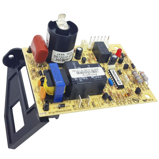
The module board acts as the brain, controlling the entire ignition sequence.
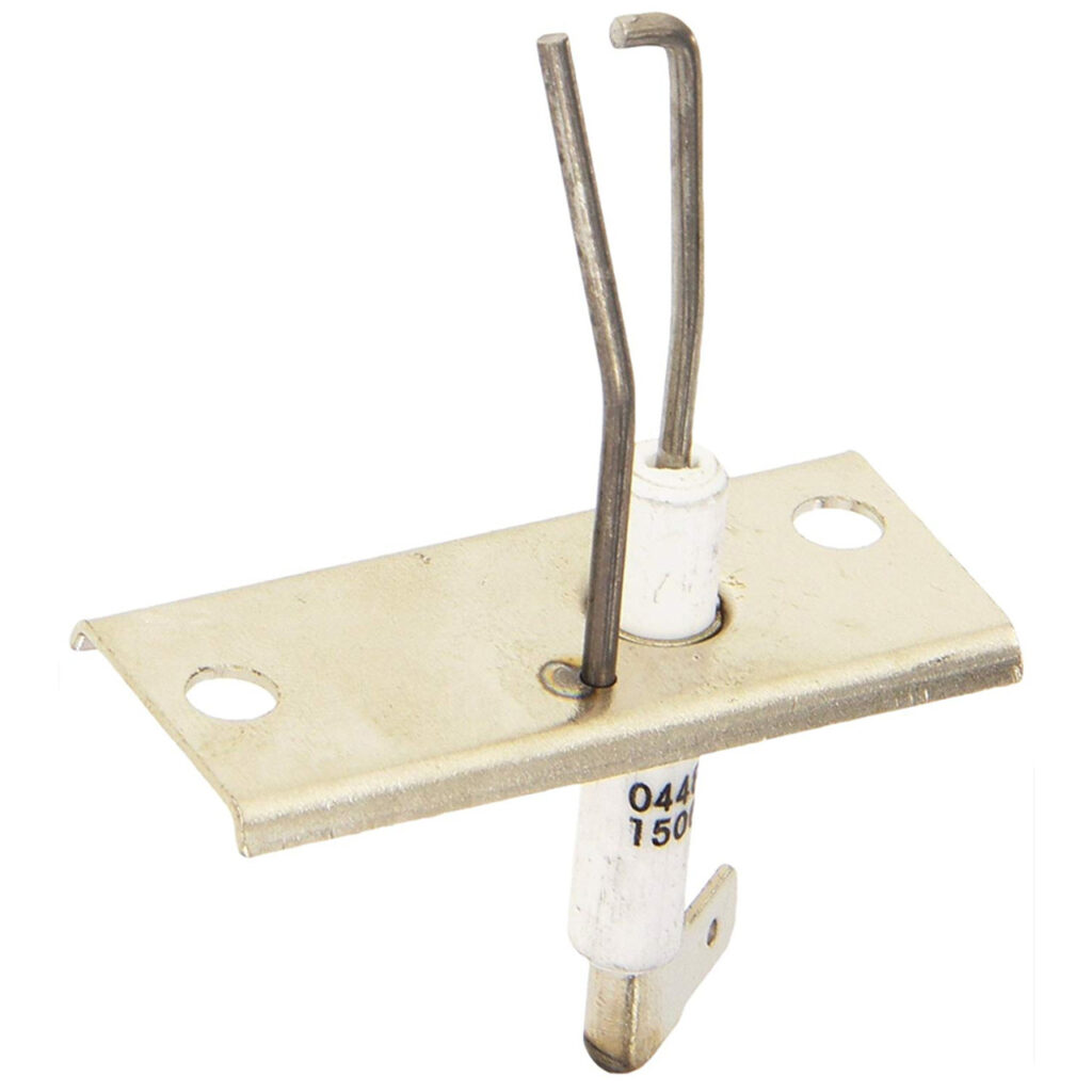
The electrode assembly includes the igniter and flame sensor.
The electrode wire transmits the high voltage from the module board to the electrode assembly, creating the spark needed for ignition.
Understanding how these components work together in a sequence is key to diagnosing problems. This guide will walk you through that sequence, from the initial call for heat to the final flame ignition.
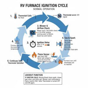 SEQUENCE OF NORMAL OPERATION The electronic ignition system is made up of three main parts: the module board, the electrode assembly, and the electrode wire. The module board is the brain of the electronic ignition system and it has several functions.
1. When the blower reaches approximately 75% of the normal rpm and sufficient airflow is established, the sail switch engages and completes a 12-volt circuit through the limit switch to the module board. (NOTE: Low-voltage power supply will not provide sufficient motor rpm to engage the sail switch.)
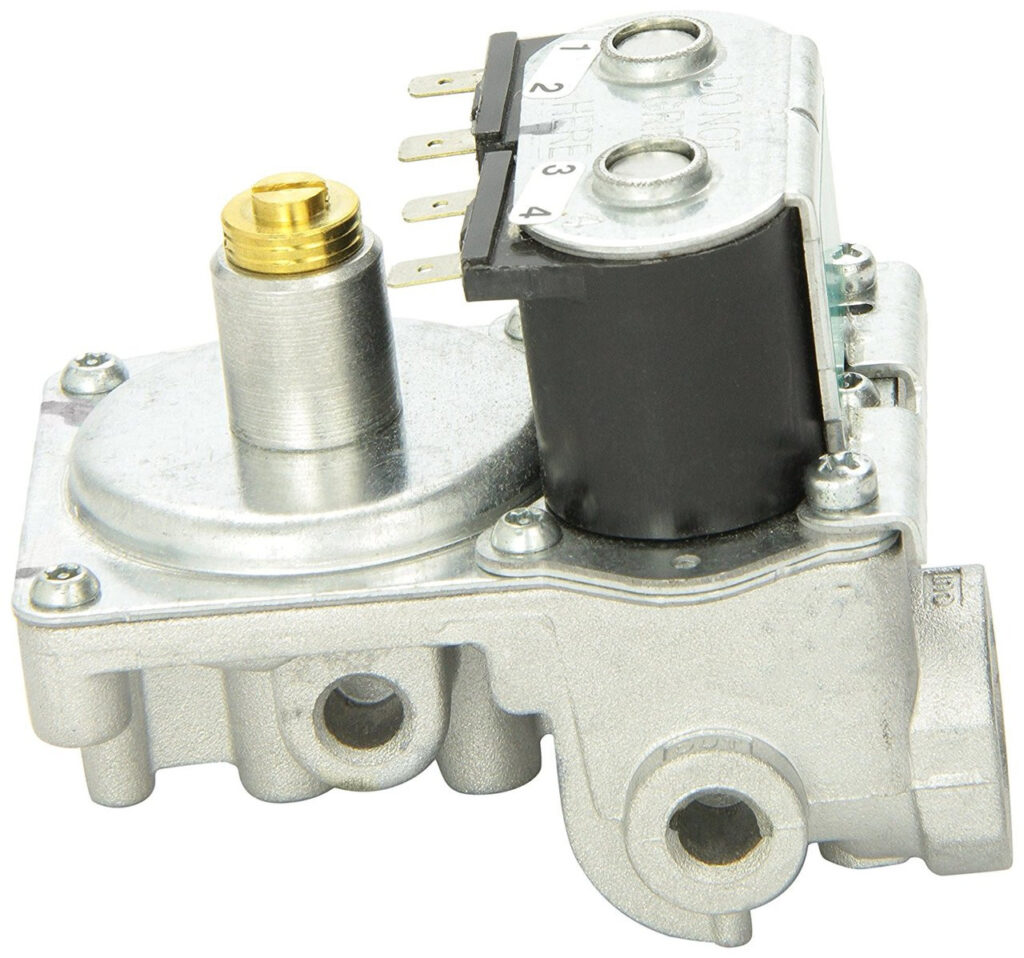
2. After a 12-18 second delay, 12-volt current will pass through the module board to the solenoid valve. The current to the valve opens it, allowing gas to reach the main burner. Simultaneously, the module board sends high voltage through the electrode wire to the electrode assembly. The voltage seeks a ground between the electrode and the ground probe, and a spark occurs. The spark then ignites the main burner.
3. The module board also performs the lockout function in cases where the spark fails to light the burner. When a lockout occurs, the spark stops, the voltage from the module board to the gas valve is discontinued, and the valve closes. The unit will remain in lockout, and the blower will continue to run until the thermostat is turned off. Turning the thermostat off disengages the lockout function of the module board. After the blower has stopped, the ignition sequence can be started again.
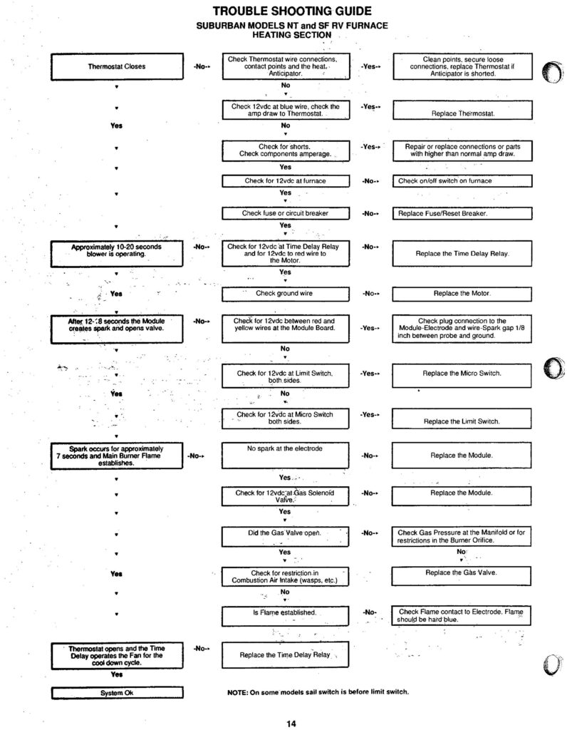
SERVICE HINTS, DIAGNOSIS, AND CORRECTIVE MEASURES FOR THE IGNITION SYSTEMS OF SUBURBAN (MOST BRANDS) 12-VOLT DC ELECTRONIC IGNITION GAS FURNACES: See Below for Main Furnace Parts
RV Furnaces with Direct Spark Ignition:
Each step in this operation must be completed in the listed order before the next function will occur. To properly diagnose a malfunction and correct it, it must be determined at what step the operation of the furnace failed.
1. When the temperature drops to a set temperature, the wall thermostat contacts close.
2. The fan relay coil is energized in the thermostat relay, completing the circuit to the blower motor. (Some models equipped with a time delay relay have a 5-25 second time delay after the thermostat contacts close).
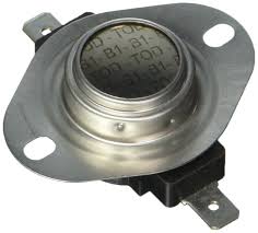
3. The motor starts and, after reaching 75% of its normal rpm, the room air blower wheel or blade activates the sail switch (microswitch), sending current to the temperature limit switch (a normally closed switch), and on to the module board.
4. When energized, the module board has a built-in 15-20 second delay, allowing the combustion air to purge the combustion chamber.
5. The module board supplies a high-voltage spark through high-tension wire to the electrode assembly, at the same time sending voltage to the gas valve, opening the valve.
6. Burner ignites.
7. The sensor probe (left probe) signals the presence of flame and the spark stops. (If flame is not established within 7 seconds, the system closes the gas valve and goes into lockout).
8. The fan switch (normally open) closes on temperature rise. This does not apply to models with the time-delay relay. These models will keep the motor running for 3 to 5 minutes by the delay of the relay.
9. The gas valve closes when either the limit switch or thermostat contacts open.
10. The blower motor goes off when the fan switch or time delay relay opens.
More Helpful Hints
Do not use a battery charger to power or test the furnace, as they sometimes provide more than the 14.5 volts DC that will damage the control module board. All testing and repair should be done by qualified personnel only. Do not use a screwdriver or touch any part of the electrode assembly while the furnace is running. Do not operate the furnace with the high-tension lead wire disconnected or the electrode assembly removed from the burner access plate.
Do not perform any high-pot tests on this furnace!
 Thermostat Is Calling For Heat, but The Blower Does Not Run:
1. Check for 12 volts DC at the furnace connection. Correct power source if “0” volts or below 12 volts DC.
2. Check all wiring for correct polarity (refer to wiring diagram), loose connections and possible shorts.
3. Check the wall thermostat and wiring for continuity. Be sure thermostat points are contacting.
4. With thermostat points closed, check for circuit completion across terminals 2 and 4 of the thermostat relay. If no continuity, and wiring to the relay is okay, replace the relay.
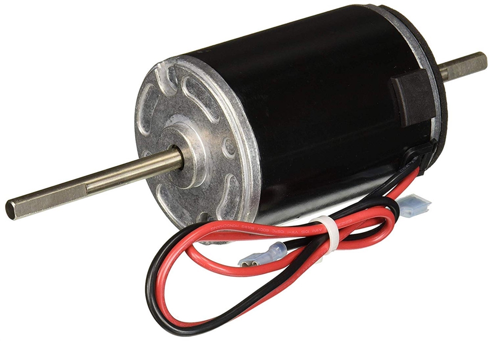
5. If there is continuity across terminals 2 and 4, and the wiring to the motor is okay, replace the motor.
6. On time delay relay models, allow 3 to 10 seconds for the circuit to be completed to the motor, as the coil in the time delay relay must heat up to close the contacts.
Blower Is Noisy:
1. Check for lint accumulation or debris on the blower wheels or possible damage to the wheel.
2. Check for excessive voltage and correct, if present.
3. Check polarity. If reversed, the motor will whine and run backward. Air delivery will be too low to close the microswitch.
4. Wheel may be hitting the housing. Remove the combustion air housing and adjust the wheel with a T-handle 1/8″ Allen wrench. On the room air wheel side, a 90* angle 1/811 Allen wrench will be needed to remove or adjust the wheel.
5. At times, insects such as mud daubers and wasps will build nests inside the combustion air housing, coming in from the fresh air intake. Remove any foreign materials and check the combustion air wheel for warpage.
6. If the bushings of the motor are worn and noise persists, replace the motor. Check both wheels for balance and, if not proper, replace the wheel or wheels.
Blower Runs but Burner Does Not Light:
1. Make sure the manual shut-off valve is in the “ON” position.
2. Possible air in the gas lines. Reset the thermostat and cycle the furnace several times to bleed the system.
3. Check the gas supply. Be certain 11″ WC pressure is present while the furnace is operating. If not, adjust the pressure regulator.
4. Check the wiring for proper polarity.
5. Check for proper clearances down the sides and across the top for return air to feed the room air blower. Each model furnace has a minimum requirement of return air outlined in the installation manual. With improper return air, the air volume may not actuate the sail switch that sends voltage to the module board. All models must have I” clearance along the sides and across the top except the NT-34, -42 and -45 models, which require 2″ on the sides and top.
6. Check the ducting of the furnace to determine proper airflow away from the furnace. See the installation manual for correct duct requirements. If the ducts have severe bends or kinks in the hose, the airflow may be restricted enough to cause the microswitch to bounce back from the volume of air hitting the cabinet front. This again will not allow voltage to the module board. Many times, a furnace will operate satisfactorily on the bench or without the cabinet door on the unit. Check for microswitch energizing when this happens. Correct ducting for proper airflow and/or replace the microswitch (could be stiff).
7. If the furnace will ignite with the cabinet front off, but will not with the cabinet front secured, and the ducting is free, check the gaskets around the burner access door. If the burner access is not properly sealed, air may be deflected from the cabinet front into the burner area, thus disturbing air and gas mixture for proper ignition.
8. Check for 12 volts DC on both sides of the limit switch. If there is voltage on one side of the switch, but not on the other, replace the switch. If voltage is present on both sides of the switch, proceed to Step 9.
9. Check for 12 volts DC at the power terminals on the module board (refer to the wiring diagram – red wire positive and yellow wire negative). If no voltage, check wiring from the limit switch. Correct wiring.
10. If sparking is audible approximately 15 seconds after the blower starts, but no ignition, check the high-tension wire for continuity, grounding and secure connections. Repair if necessary.
11. Make sure electrode is not grounding to burner, the gap between the spark probe and the ground probe is 1/8″ (see Figure 7), and the ceramic insulator is not cracked, broken or sooted. Adjust, clean or replace as necessary.
12. If sparking is not audible, check the module board and observe if the neon bulb on the circuit board is flashing during the trial for ignition. Remove the white plastic wire connector from the circuit board. Clean the board terminals on back with a soft rubber eraser. Check the little pin terminals in the plastic connector for good contact. Reinstall connector. If the tube does not flash, replace the module board.
13. Check for voltage at the gas valve during the trial for ignition. If no voltage and connections are okay, replace the board.
14. If the valve does not open with 12 volts DC present, replace the valve.
15. If the electrode sparks and the valve opens but the burner will not light, check the gas supply for 11″ WC pressure to the main burner office. If 11″ is present to the valve but not to the orifice, replace the valve. Check vent and air intake installation. Check the main burner for correct relationship to the electrode assembly (burner should be 3/16″ from the spark probe and sawports or charge ports directly under the spark gap). Check main burner for soot build-up in ports (see Figure 8). Clean cast-iron burners by passing a hacksaw blade through the sawports, being careful not to enlarge the openings. Wire brush stainless tube burners to remove build-up.
16. Check the combustion air wheel for proper rotation. Insufficient air will not sustain the flame if the wheel is installed backward.
Burner Ignites But Shuts Off:
1. Check to be certain that flame sensor is over slots in the main burner and that the main burner flame is burning against the tip of the flame sensor – adjust by bending the sensor probe. NOTE: Sensor probe should be in the inner blue cone of the burner flame, approximately 1/4″ to 5/16″ above the burner.
2. If the burner still goes off and into lockout, check the wire connections at the flame sensor and the module board.
3. If wire connections are okay, check for continuity through the flame sensor wire.
4. If the continuity of the flame sensor wire is okay, check with microamp meter in series with the flame sensor and flame sensor wire to be certain the flame sensor is generating at least seven microamps within seven seconds after the burner is ignited. Connect the meter as follows: (+) to sensor wire, (-) to sensor probe. Adjust the position of the sensor probe, check air adjustment and check for carbon deposits on the sensor probe if the reading is less than seven microamps.
5. When the flame sensor circuit is generating at least seven microamps, but the burner still goes off and into lockout, replace the module board.
Main Burner Will Not Shut Off:
1. Make sure the thermostat and contact points are open.
2. Check voltage at the valve terminals – should be “0” voltage.
3. Disconnect leads from the valve. If it does not shut off, replace the valve.
Continuous Sparking Of the Electrode:
1. Check the sensor wire and high-tension wire for good connections. Check for separations in either wire – repair or replace. Check to be certain that the flame sensor probe is over the slots in the main burner and that the main burner flame is burning against the tip of the sensor probe. Adjust by bending the probe or repositioning the burner. The burner flame should be a hard blue flame, lying down on the burner.
Erratic Blower and/or Thermostat Operation:
1. Check the wiring to the furnace.
2. Check for shorts in wiring.
3. Disconnect leads to the gas valve. If the furnace runs properly with the leads removed, replace the gas valve.
4. If the fan continues to run after the thermostat is satisfied and the burner goes off, the fan switch or the time delay relay is defective and needs to be replace. If the fan comes back on after a short period of time (within one minute) and cuts off and on, replace the fan switch.
5. If the thermostat is not satisfied (points still made) and the fan cuts on and off, replace the motor (thermal overload switch is defective.)
Unit Going Into Lockout Only Once In A While:
1. Thoroughly check the electrode and burner air adjustments.
2. Lockout can occur if the gas pressure fluctuates at the time that the thermostat calls for heat. Pressure fluctuations can be caused by a malfunctioning gas bottle regulator, and obstruction or a kink in the gas line, or moisture in the gas bottle
regulator or in the gas lines. It is difficult to check for these fluctuations that will not noticeably affect any other appliance in the coach. However, isolating the furnace from the coach gas system will determine if the gas system is responsible. This
isolation procedure can be done by connecting a separate upright bottle, regulator and gas line directly to the furnace, eliminating the coach gas system. If the occasional lockout still exists, then the furnace should be thoroughly tested to
determine the cause; however, if the furnace works properly on this separate system, then the coach gas system should be checked.
3. Check the furnace return air and warm air discharge to be certain sufficient airflow is present to engage the microswitch every time.
4. Check the microswitch to be sure it moves freely.
5. Remove the electrode and burner and clean them thoroughly.
6. When moisture in the gas system is suspected as being the problem, especially where the horizontal type gas bottle is being used, the following steps should be taken to prepare the gas system against further moisture problems.
Corrective Measures:
1. Disconnect gas bottle and drain it completely dry of all gas and all moisture.
2. Disconnect and blow out all gas lines completely dry.
3. Check pressure regulator on the gas bottle. Replace if necessary.
4. Add the drying agent. One half pint of methanol alcohol per 100 pound bottle capacity is recommended.
Precautions:
1. Never fill the gas bottle over 80%.
2. Do not use the gas bottle completely dry to avoid using up the drying agent. We have found the above procedures to be effective in solving most occasional lockout problems; especially where the horizontal-type gas bottle is used. All of these steps must be performed as described for the preparation of a contaminated gas system to be 100%
effective.
Repeated Module Board Failures:
1. Check to be certain that the electrode spark is not sparking against the flame sensor portion of the electrode assembly.
2. Check to be sure the module board or high voltage wires are not shorted to the chamber wrapper or other furnace parts.
3. Be sure the insulator covering the electrode wire connection on the coil of the module board is in place and the insulator behind the module board is in place.
4. Check the high voltage – 14.5 volts DC maximum. High voltage can intermittently produce voltage surges or AC spikes, which can damage the module board. The supply voltage to the furnace should be checked if repeated module board failures occur.
5. Be sure duct connections to the furnace are airtight. Seal duct collar connections to the furnace cabinet with duct tape, if necessary, to prevent hot air leakage. No air leakage should exist anywhere in the duct system, especially at connections on the furnace cabinet.
6. The high-voltage electrode wire should be routed away from any 12-volt wires (except at the grommet for the sensor wire). No wires should pass over the module board.
7. Be sure the sensor wire terminal is tightly affixed to the sensor probe.
8. Be sure high voltage electrode wire is in good condition and properly positioned onto pierce point electrode or spade terminal.